The enforcement of spectral criteria in radar systems is
significantly dependent upon the configuration used for spectrum
measurement. Regulatory agencies must provide standards for the spectrum
measurement. The international regulatory body for spectrum regulations
is the International Telecommunication Union (ITU). Several ITU
standards exist in describing allowable emissions and the measurement
assessment of spectral compliance. Standard ITU-R SM.329 discusses allowable emissions in the spurious emission domain [1],
and standard ITU-R SM.1541 describes allowable emissions in the
out-of-band (OoB) domain, which is closer to the assigned bandwidth than
the spurious domain [2].
In light of these standards, an additional standard ITU-R M.1177-4
provides recommended settings for the measurement of emissions [3]. The ITU Radio Regulations provide the spectral limitations of transmitted radio signals [4]. In addition, individual nations have regulatory agencies that often expound upon the ITU standards for spectrum regulation.
In U.S., the National Telecommunications and Information Administration
(NTIA) sets guidelines for the spectrum properties in the radar
spectrum emissions criteria (RSEC) [5].
In addition to the RSEC, the NTIA has released a report by one of the
authors detailing procedures for measurement assessment of RSEC
compliance [6] and a report discussing receiver measurement bandwidth issues related to receivers [7].
These criteria indicate measurement settings for evaluation of the
spectrum and also bandwidth issues related to chirp waveforms for
detrimental effects of interference. Among these criteria are maximum
limits on the bandwidths that should be used to measure pulsed radar
emission spectra. A topic not addressed in this existing literature, but
which is addressed in this paper, is the justification for the maximum
measurement bandwidth limits for linear frequency-modulation (LFM)
waveforms, also known as “chirps.” While the ITU and NTIA standards
provide recommendations for settings such as resolution bandwidth, our
paper provides experimental data explaining the importance of these
settings and connects the measurement science with the
compliance-measurement recommendations. To our knowledge, this paper is
the first to comprehensively address the issue of radar spectrum
measurements for compliance from a measurement science perspective with
experimental motivation and validation. We provide specific measurement
examples of chirp waveforms and discuss, based on our experimental
results, how changing the settings can adversely affect the measurement
data, and possibly a compliance determination.
Linear chirps are useful radar waveforms
because they provide improvement on range resolution for a given pulse
length due to the ability to compress the pulse [8].
In radar system operation, a burst of a sinusoid with increasing or
decreasing frequency will happen during the radar's “transmit” time, and
then the transmitter will hibernate during the “listen” time. The
periodicity of the waveform produces a spectrum in which power is
concentrated at a finite number of frequencies (a discrete spectrum).
The need for accurate and standardized spectrum measurement
procedures is motivated by increasingly stringent spectral requirements
on radar systems. In a struggling international economy, wireless
broadband applications show promise in providing significant financial
return. As such, new developments such as the U.S. President's Broadband Plan [9]
are requiring that additional spectrum be allocated for wireless
broadband use. Such developments are requiring radar transmitters to
operate in narrower slices of spectrum. In the RSEC, the NTIA sets spectral masks in the U.S. within which radar signals are required to be confined [10], as shown in Fig. 1.
Allocations are pushing the technical limits of operation for presently
used legacy radar systems. The line of the mask shown in Fig. 1
allows a 40-dB bandwidth of 16 MHz; this means that at 8 MHz
from the center frequency on each side, the signal must be reduced by
40 dB from its maximum in-band value. The mask then specifies that,
outside of the 16 MHz bandwidth, the maximum signal level
decreases at a rate of 20 dB per frequency decade away from the
band.
In
addition to fixed measurement systems, standard methods of measurement
will be essential in the real-time assessment and tuning of future
adaptive radar systems [11]– [12] [13][14]. Our previous work has detailed a test platform [15]
to perform such measurements and develop techniques with a goal of
eventual integration into a real-time, adaptive radar system.
Some work exists in the open literature related to measurement evaluation of spectra for different applications. Engelson discusses the measurement of code-division multiple access (CDMA) signals in [16]. Agilent Technologies [17]
examines settings for measuring different types of signals and provides
resolution and video bandwidth recommendations for different scenarios.
Bertocco discusses the measurement of power using a spectrum analyzer
from the “channel-power” and “zero-span” approaches, noting that
resolution bandwidth in a channel-power approach should be narrow enough
to resolve individual spectral components if a measurement of peak
power is desired [18]. He also notes that if a
zero-span measurement of power is desired, the resolution bandwidth
should be at least as large as the signal bandwidth to avoid
underestimation of the signal power. While providing useful information
about spectrum analyzer settings for different desired evaluations,
Bertocco's treatment is focused on power measurements, rather than
measurements to determine spectral compliance. In [19],
Bertocco gives some theoretical considerations and discussion related
to practical spectrum analyzer measurements, stating that several
spectral components will fall into the filter passband simultaneously
for the case of a line spectrum if the resolution filter bandwidth is
wider than the spectral line separation, also discussed by [20]. Bertocco et al. [19] also discusses the use of peak detectors to perform sampling.
Multiple studies have also been performed on spectrum occupancy of
different regional areas, with a view to the assessment of cognitive
radio and dynamic spectrum access feasibility [21]– [22][23].
The challenge of setting a measured power threshold to label a region
of spectrum as “occupied” is dealt with by Islam, who used a level of
6 dB over the minimum received power [21].
Wellens states that a decision threshold of 3 dB higher than the
measured noise floor was expected to result, in his study, in a
false-alarm probability of about 1% [22].
Sanders, in evaluating spectrum occupancy, suggests the use of
resolution bandwidth equal to the span, allowing each spectral content
to be represented exactly once in the measurement [23].
This consideration of resolution bandwidth is one that we readdress in
this paper, but with a view toward determining spectral compliance, a
distinct application from other relevant papers.
The ITU standards also provide information related to measurements
for spectral compliance. Standard ITU-R SM.329 describes reference
bandwidth as the bandwidth in which the acceptable power is specified,
and resolution bandwidth as the bandwidth used by the spectrum analyzer
for measurement. This standard states that “narrower resolution
bandwidth is sometimes necessary for emissions close to the center
frequency.” ITU-R SM.1541 [1]
describes the assessment of emissions in the OoB domain, usually the
region adjacent to the main channel that is affected by
nonlinearity-induced intermodulation distortion. It defines the idea of adjacent-band power ratio as a useful measurement for assessing OoB power [2]. Finally, ITU-R M.1177-4 recommends techniques for the measurement of the emitted spectrum based on [1] and [2]. It also gives specific information on performing measurements close to the band of operation [3].
This paper presents the theory and measurement verification for the
regulatory spectrum analysis of radar signals. It examines spectrum
analysis considerations specifically for spectral compliance
measurements. The work presented in this paper is significant because it
provides a distinct look at the impact of spectrum analysis measurement
considerations on spectral compliance evaluations. While the ITU
standards provide some level of guidance on performing the measurements,
the purpose of this paper is to provide understanding and experimental
data to the measurement assessment of spectral compliance. This paper
uniquely describes not only the “what” and “how” of spectrum
measurements, but also addresses the question of “why” certain settings
must be used to ensure accurate compliance determinations.
SECTION II
CHIRP WAVEFORM ANALYSIS
During the “on” time of the transmitter pulse, a linear FM chirp has a linear time-frequency description. Fig. 2 depicts the frequency-versus-time characteristic. The frequency sweep begins at  $f_{L}$ and ends at
  $f_{H}$. As such the spectrum of the chirp will span the frequency range from
  $f_{L}$ to
  $f_{H}$.
Because this pulsed chirp waveform is periodic, its spectrum will be
discrete, consisting of impulse functions at integer multiples of the
fundamental frequency. If the period of an entire on-off cycle of the
chirp is given as
$f_{H}$.
Because this pulsed chirp waveform is periodic, its spectrum will be
discrete, consisting of impulse functions at integer multiples of the
fundamental frequency. If the period of an entire on-off cycle of the
chirp is given as  $T$, then the fundamental frequency is
  TeX Source$$f_m = {1 \over T}.\eqno{\hbox{(1)}}$$
As a result, the spacing between tones in the chirp spectrum is  $f_{m}$ [24].
Understanding that the spectrum of periodically repeated chirps is
actually discrete is critical to the interpretation of measurement data
in which the spectrum appears to be continous. This appearance does not
represent the actual shape of the spectrum, but is an artifact of the
spectrum analyzer measurement.
To illustrate an effective general measurement methodology, a simple
case study is performed on measurements for a linear FM (LFM) chirp with
16 MHz swept bandwidth. We examine the same chirp for different
measurement settings and assess potential issues in assessing the
measurements, as well as using the chirp settings to plot a course for
making desired measurements.
The complex exponential version of the LFM chirp waveform during the “on” time of the duty cycle is given as  TeX Source$$w\left(t \right) = \hbox{exp}\left({j\omega t} \right).\eqno{\hbox{(2)}}$$
The instantaneous frequency is a linear function of time and is expressed as follows, where  $\omega _0$ is the radian frequency at
  $t$ = 0 and
  $2\mu$ is the slope of the radian frequency-versus-time characteristic (this means that
  ${\mu}$/
 ${\pi}$ is the Hertz frequency-versus-time slope)
  TeX Source$$\omega = {{d\phi \over dt}} = \omega _0 + 2\mu t.\eqno{\hbox{(3)}}$$
The linear frequency-versus-time characteristic has a low-frequency limit  TeX Source$$f_L = {{\omega _0 \over 2\pi}}\eqno{\hbox{(4)}}$$ and high-frequency limit
  TeX Source$$f_H = {{\omega _0 + 2\mu \tau \over 2\pi}}\eqno{\hbox{(5)}}$$ where
  ${\tau}$ is the “on-time” pulse width of the chirp burst.
Table I provides information about the
chirp settings for the running example used in this paper: 16 MHz
chirp range, 3.3 GHz center frequency, and 30 kHz waveform
repetition rate. For the purpose of the measurements presented, the
chirp burst time τ was made to be equal to the chirp repetition time  $T$;
that is, a duty cycle of 100 percent was used for the measured
waveform. The slope of the frequency-versus-time characteristic is then 2
$T$;
that is, a duty cycle of 100 percent was used for the measured
waveform. The slope of the frequency-versus-time characteristic is then 2
 ${\mu}$, where
  ${\mu}$ is found by solving (5) for
  ${\mu}$ using these settings, giving
 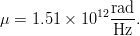 TeX Source$$\mu = 1.51 \times 10^{12} {{{\rm rad} \over {\rm Hz}}}.$$ The linear chirp rate in Hertz per second is
 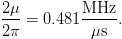 TeX Source$${{2\mu \over 2\pi}} = 0.481{{{\rm MHz} \over {\rm \mu s}}}.$$
SECTION III
SPECTRUM ANALYZER MEASUREMENTS
A simplified block diagram model of a spectrum analyzer measurement is shown in Fig. 3
This diagram has been simplified to illustrate the functionality of
systems important to these measurements; for a more detailed diagram,
the reader is referred to [17]. The signal to be
measured is input to a mixer. A swept local oscillator is used to
down-convert the measured RF signal to an intermediate frequency (IF).
The IF resolution bandwidth filter, centered at the fixed IF, reports
the power captured within its bandwidth and plots a representative point
on the spectrum analyzer display. The swept oscillator is synchronized
with the trace frequency on the spectrum analyzer display. The total
power reported for a given frequency on the spectrum analyzer is the
power that falls within the bandwidth of the IF filter.
The resolution bandwidth is of central importance in the measurement
of a wideband signal, such as the LFM chirp. Because the signal is
wideband, the power contained within the filter bandwidth increases as
the bandwidth increases. This is underscored in
the ITU standard ITU-R M.1177-4, which suggests for some simple
modulations that the measurement bandwidth be less than the tone
spacing, so that only one tone of the spectrum will be included in any
measurement [3]. The following describe different resolution bandwidth scenarios for measurement:
- Narrow resolution bandwidth. If the bandwidth is sufficiently
narrow, each of the discrete tones will be captured with a shape that is
similar to the shape of the filter.
- Wider resolution bandwidth. Wider resolution bandwidth may allow
multiple tones to be captured inside the filter. If the filter bandwidth
is wide enough to contain multiple tones in each measurement, then the
total power will never reach zero.
- Very wide resolution bandwidth. When the filter bandwidth is much
larger than the tone spacing, the power measurement will produce a
result that is nearly flat with frequency and has a power value
consistent with the total power in the band at each measured frequency
point.
SECTION IV
MEASUREMENT RESULTS
This section evaluates the dependence of the measured spectrum upon
resolution bandwidth and number of points used. It then outlines a
recommended procedure for spectral compliance measurements.
A. Effect of Resolution Bandwidth Setting
Measurements were performed with the spectrum analyzer to illustrate
the dependence of the measurement data on the resolution bandwidth
setting. The chirp waveform, with settings as shown in Table I,
was generated in the laboratory using an Agilent N5182 MXG vector
signal generator. To generate the waveform, the in-phase and quadrature
component definitions of the waveform were created in MATLAB, and the
waveform was created by the signal generator by playing the defined
samples at a rate of 60 megasamples per second. The repetition rate of
the entire chirp waveform is therefore dependent on the number of
samples for one complete cycle of the chirp. For a chirp defined using
2000 samples and the instrument clock rate of 60 megasamples per second,
the fundamental chirp repetition frequency is given by 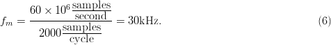 TeX Source$$f_m
= {{60 \times 10^6 {{\hbox{samples} \over \hbox{second}}} \over
2000{{\hbox{samples} \over \hbox{cycle}}}}} =
30\hbox{kHz}.\eqno{\hbox{(6)}}$$
TeX Source$$f_m
= {{60 \times 10^6 {{\hbox{samples} \over \hbox{second}}} \over
2000{{\hbox{samples} \over \hbox{cycle}}}}} =
30\hbox{kHz}.\eqno{\hbox{(6)}}$$
Fig. 4(a) shows the resultant spectrum
analyzer measurement with a narrow IF bandwidth. In this measurement,
the individual tones are spaced by 30 kHz.
A second measurement was taken with the same chirp rates, but with
the waveform defined over only 500 samples. In this case, the
fundamental chirp repetition frequency is given by 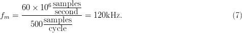 TeX Source$$f_m
= {{60 \times 10^6 {{\hbox{samples} \over \hbox{second}}} \over
500{{\hbox{samples} \over \hbox{cycle}}}}} =
120\hbox{kHz.}\eqno{\hbox{(7)}}$$
TeX Source$$f_m
= {{60 \times 10^6 {{\hbox{samples} \over \hbox{second}}} \over
500{{\hbox{samples} \over \hbox{cycle}}}}} =
120\hbox{kHz.}\eqno{\hbox{(7)}}$$
Results for the measurement of this chirp are shown in Fig. 4(b).
In this case, the tones are spaced by 120 kHz, as expected. The
remainder of the experimental results shown in this paper is for
30 kHz tone spacing [as in Fig. 4(a)], given by Table I.
Fig. 5 shows measurement results for three
resolution bandwidth values for spectral tone spacing (fundamental
frequency) of 30 kHz.
- Resolution Bandwidth Smaller Than the Tone Spacing (10 kHz) : Fig. 5(a)
shows the results for 10- kHz resolution bandwidth. In this case, the
resolution bandwidth is significantly smaller than the tone spacing, so
no more than one tone will be present in the measurement IF bandwidth at
any measurement instant.
- Resolution Bandwidth Equal to the Tone Spacing (30 kHz): Fig. 5(b)
gives measurement results for a resolution bandwidth of 30 kHz. In
this case, the resolution bandwidth is equal to the separation of the
tones to be measured, so as one tone leaves the measurement bandwidth,
another enters. The nulls between the measured peaks for a resolution
bandwidth of 30 kHz are not as deep as the nulls for a resolution
bandwidth of 10 kHz.
- Resolution Bandwidth Greater Than the Tone Spacing (100 kHz): Fig. 5(c)
shows the measured spectrum power for 100 kHz resolution
bandwidth. In this case, the measurement bandwidth is much wider than
the tone separation. The IF filter contains at most four tones and at
least three tones for each measured data point. The variation between
the Watt power in a bandwidth should not be more than 25 percent of the
maximum. This corresponds to an expected variation that is within
approximately +/−1.25 dB. Fig. 5(c) shows
a variation on this order. The slight variation is based on whether
three or four tones are within the resolution bandwidth at each measured
point.
As the resolution bandwidth is increased, the variation between
measured points will decrease even further. The ripple versus frequency
as the filter moves to measure each point reduces as the number of tones
in the bandwidth becomes larger. Fig. 6 shows
the results for a broader frequency span, revealing the measurement of
the entire chirp spectrum, using resolution bandwidths of 100, 5, and
1 kHz.
- Large (100 kHz) Resolution Bandwidth: For 100 kHz resolution bandwidth [see Fig. 6(a)],
the power value in the band is much larger, the in-band characteristic
is very flat, the apparent bandwidth is much larger than the chirp
bandwidth of 16 MHz, and the OoB degradation is gradual. The large
resolution bandwidth for the 100 kHz setting allows multiple tones
to appear within the bandwidth at each measured point, causing the
measured power level to appear very high (−19.1 dBm) in the band. This
also accounts for the gradual OoB degradation, as even with a center
frequency out of the band of the chirp, multiple tones from inside the
chirp bandwidth may still appear within the filter's resolution
bandwidth.
- Medium (5 kHz) Resolution Bandwidth: Fig. 6(b)
shows the same 16 MHz chirp measured with a resolution bandwidth
of 5 kHz, one-twentieth the size of the previous case. The in-band
measurement shows small ripples, the apparent chirp bandwidth is
narrower, the measured power in the band is significantly lower (−37.82
dBm), and the OoB rolloff is smoother and much quicker.
- Small (1 kHz) Resolution Bandwidth: Fig. 6(c)
shows the results for an even narrower resolution bandwidth
(1 kHz), and it can be seen that the measured in-band power is
approximately −40 dBm. A reduced noise floor is also evident. Because
the measured noise power is equal to kTB, where
 $k$ is Boltzmann's constant,
  $T$ is the Kelvin temperature, and
  $B$
is the Hz bandwidth, the noise floor is expected to decrease as the
resolution bandwidth is decreased. This shows details in the actual
spectral spreading that would be lost by a measurement with wider
resolution bandwidth.
$B$
is the Hz bandwidth, the noise floor is expected to decrease as the
resolution bandwidth is decreased. This shows details in the actual
spectral spreading that would be lost by a measurement with wider
resolution bandwidth.
ITU standard ITU-R M.1177-4 specifically refers to the situation shown in the following passage found in the standard [3]:
“Measurements should generally be made using a bandwidth that is
close to but less than the specified reference bandwidth. This approach
will minimize the measurement time but it also causes some broadening of
the measured spectrum. Thus in marginal situations, where measurement
of the true close in spectrum shape may be important, it is recommended
that the close-in region within the OoB domain should be measured using a
maximum bandwidth of 0.2/T or 0.2/t as appropriate.”
The “broadening of the measured spectrum” is seen when a large measurement spectrum is used, such as in Fig. 6(a). In the case of this chirp, the tone spacing is 30 kHz (this is 1/ $T$), so the recommended measurement bandwidth based on this ITU-R M.1177-4 passage is
 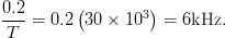 TeX Source$${{0.2} \over T} = 0.2\left({30 \times 10^3 } \right) = 6\hbox{kHz.}$$
This means that both Fig. 6(b) (resolution
bandwidth = 5 kHz) and (c) (1 kHz) are acceptable in regard to
limitation of spectral spreading for compliance purposes. However, the
smaller resolution bandwidth in the measurement of Fig. 6(c) has a lower noise floor, which may be necessary if the spectral mask evaluation requires measurement of low power levels.
B. Effect of Measured Points Number
Fig. 7 shows the same chirp as is displayed in Fig. 6, measured with a varying number of points. Fig. 7(a) shows the results for 401 points, Fig. 7(b) shows results for 1601 points, and Fig. 7(c) shows the measured spectrum for 6601 points. No in-band null points are seen in Fig. 7(a), but a significant number of nulls is visible in the measurement of Fig. 7(b), and Fig. 7(c) shows an even greater number of nulls.
An understanding of the video stage of the spectrum-analyzer front-end, as described in a very useful Agilent application note [17],
assists in interpreting these results. The local oscillator is tuned by
the voltage output of a sweep generator. As a result, spectral content
over the range of RF frequencies to be measured is downconverted and
swept through the resolution-bandwidth filter at the IF.
The signal is then passed through an envelope detector, which
provides a measurement of the power inside the filter. The video
bandwidth filter follows, followed by a peak-sample-hold circuit. When
the spectrum analyzer is in peak measurement mode (as for the results
shown in this paper), this circuit reports the peak value of the sweep
surrounding each measured point on the spectrum analyzer screen.
1. Small Number of Measured Points (401)
For all three measurements shown in Fig. 7, the span can be seen to be 100 MHz (3.25−3.35 GHz). For the 401-point measurement of Fig. 7(a),
a total of 401 points was used. This means that the frequency spacing
between measured data points, and equivalently, the frequency interval
over which a peak value is sampled, here called Δ  $f_{\rm data}$, is
  TeX Source$$\Delta
f_{{\rm data}} = {{100\hbox{MHz} \over 400\hbox{intervals}}} =
250{{\hbox{kHz} \over \hbox{interval}}}.\eqno{\hbox{(8)}}$$
TeX Source$$\Delta
f_{{\rm data}} = {{100\hbox{MHz} \over 400\hbox{intervals}}} =
250{{\hbox{kHz} \over \hbox{interval}}}.\eqno{\hbox{(8)}}$$
Thus, for each measured data point, an interval of 250 kHz is
swept with a resolution bandwidth of 1 kHz and the peak value
reported through the “sample-and-hold” approach. The results are
connected on the spectrum analyzer output. Because the tones for this
measurement are spaced by  $f_{m}$
= 30 kHz, at least eight tones appear in each sampled range. The
maximum value measured for these tones will be recorded. This is why no
nulls appear in the 401-points result of Fig. 7(a).
$f_{m}$
= 30 kHz, at least eight tones appear in each sampled range. The
maximum value measured for these tones will be recorded. This is why no
nulls appear in the 401-points result of Fig. 7(a).
2. Moderate Number of Measured Points (1601)
For the measurement of Fig. 7(b), a total of 1601 points was used. This means that the value for Δ $f_{\rm data}$ is
  TeX Source$$\Delta
f_{{\rm data}} = {{100\hbox{MHz} \over 1600\hbox{intervals}}} =
62.5{{\hbox{kHz} \over \hbox{interval}}}.\eqno{\hbox{(9)}}$$
TeX Source$$\Delta
f_{{\rm data}} = {{100\hbox{MHz} \over 1600\hbox{intervals}}} =
62.5{{\hbox{kHz} \over \hbox{interval}}}.\eqno{\hbox{(9)}}$$
Because the tone spacing is 30 kHz, it is expected that most
intervals will contain at least two tones. Because the resolution
bandwidth is narrow, however, the power levels reported at the points
are expected to be the similar to the 401-point measurement of Fig. 7(a). The plot of Fig. 7(b)
contains more noise, as the maximum in each region is taken over only
two measured tones, rather than 8. This increases the variation of the
maximum-value measurements from point to point.
3. Large Number of Measured Points (6601)
Fig. 7(c) contains the largest number of null points. In this case, the value of Δ $f_{\rm data}$ is
  TeX Source$$\Delta
f_{{\rm data}} = {{100\hbox{MHz} \over 6600\hbox{intervals}}} =
15.15{{\hbox{kHz} \over \hbox{interval}}}.\eqno{\hbox{(10)}}$$
TeX Source$$\Delta
f_{{\rm data}} = {{100\hbox{MHz} \over 6600\hbox{intervals}}} =
15.15{{\hbox{kHz} \over \hbox{interval}}}.\eqno{\hbox{(10)}}$$
For a tone spacing of 15.15 kHz, the probability that a tone
will be detected in a given sweep range is approximately only 50%, and
so the number of zero measurements, or “nulls,” is expected to be
significant. Commensurate with this expectation, Fig. 7(c) shows a measurement containing many zeros.
While it is interesting from a spectrum analyzer to see the locations
of the tones and nulls, the identification of individual tones and
their locations is not critical in the measurement of chirps for
spectral compliance assessment. The outline of the spectral shape is
more clearly seen in the graph of Fig. 6(a) than in Fig. 6(b) and (c).
The shape is most easily and accurately seen when the number of points
is small enough that at least one tone is contained in each measurement
window. Optimally, the resolution bandwidth will be small enough that
the IF filter passband never contains more than one tone at any point
during the measurement. Measurements such as those shown in Fig. 6(c) and 7(a) are best for assessing compliance with RSEC or other spectrum evaluation criteria.
SECTION V
GUIDELINES FOR SPECTRAL COMPLIANCE MEASUREMENTS
As shown in the measurement results, the resolution bandwidth and
number of points have a significant impact on the measured data. How the
data are measured can have an impact on whether the signal appears to
meet the spectral mask requirements or to fail compliance. Based on the
experiments shown, some general guidelines for spectral compliance
measurements are given in this section. For all measurements, the span
should be set large enough to view the desired channel and adjacent
channels under consideration.
A. Resolution Bandwidth
If possible, the resolution bandwidth should be set to a small enough
value that only one tone is present in the resolution bandwidth for
each measurement. In most cases, this is several orders of magnitude
smaller than the assigned channel bandwidth. The measurement of power at
each prespecified frequency is the total power in the resolution
bandwidth centered around this frequency. As such, a small bandwidth
should be used surrounding each measurement point.
The danger of setting the resolution bandwidth too large is that
power will be reported at a given frequency that is actually from
spectral content a significant distance from that frequency. This is referred to by ITU-R M.1177-4 as “broadening of the measurement spectrum,” [3] and could result in an improper determination of spectral compliance. Fig. 6(a)
is an example of a measurement where this undesirable effect occurs. A
resolution bandwidth of 100 kHz was used for this measurement,
meaning that spectral content is included at each measured point for
50 kHz on both sides of the reported frequency. Because the
repetition frequency of the chirp in these measurements is 30 kHz,
this means that either 3 or 4 tones will be present in the resolution
bandwidth for each measurement. This causes apparent “spreading” of the
signal, and could cause a radar system to be declared as noncompliant,
when, in fact, its power actually resides within the spectral mask. An
erroneous declaration of noncompliance could result in the prevention of
a compliant system from being put into operation at great cost to both
the manufacturer and the end user. For ideal spectral compliance
measurements, the resolution bandwidth should be less than the tone
spacing (in the case of the experiments shown, less than 30 kHz). ITU-R M.1177-4 recommends that an even smaller value of 0.2/ $T$ should be used, where
  $T$ is the period of the waveform [3]. This corresponds to 6 kHz for Fig. 6 example.
A second artifact of using a smaller resolution bandwidth is that it causes the noise floor to be lower.
ITU-R M.1177-4 states “To obtain a complete picture of the spectrum
especially in the spurious emission domain, it is recommended to be able
to measure levels of emissions 10 dB below the levels given in RR
(ITU Radio Regulation) Appendix 3” [3]. The
spurious emission domain contains frequencies some distance away from
the main channel, and these are usually required to have much lower
power values than the in-band signal. For example, if the signal is
required to be 50 dB down from the maximum in-band power at the
alternate channel, but the spectrum analyzer measurement shows a noise
floor that is only 40 dB down from this maximum in-band power, mask
compliance cannot be assessed. Based on ITU-R M.1177-4, the noise floor
must be reduced by 20 dB to give 10 dB between the mask value
and the noise floor. From noise measurement theory, the noise floor changes based on the resolution bandwidth as follows [25]:  TeX Source$$\Delta N\left({dB} \right) = 10\log (B_{{\rm factor}})\eqno{\hbox{(11)}}$$ where
  $\Delta N$ is the change in dB of the noise floor, and
  $B_{{\rm factor}}$ is the factor by which the resolution bandwidth is multiplied. Solving for
  $B_{{\rm factor}}$ for
  $\Delta N = - 20$ dB gives
  TeX Source$$B_{{\rm factor}} = 10^{\Delta N\left({dB} \right)/10} = 10^{- {{20 \over 10}}} = 0.01.$$
Thus, reducing the resolution bandwidth by a factor of 100 will provide a noise floor reduction of 20 dB.
If the resolution bandwidth is very small, the sweep time will be
very large, and taking the data necessary for the measurements will
become an inefficient process. Thus, the resolution bandwidth should
simply be set low enough so that (1) only one tone exists in the resolution bandwidth filter for each measurement and (2)
the measurement noise floor is low enough to assess the compliance for
the OoB frequencies of interest. However, requiring the resolution
bandwidth to be lower than this will unnecessarily slow the measurement.
B. Number of Measured Points
The tones in a spectrum are spaced by the repetition rate of the
radar chirp. If peak measurement mode is used, then as long as the
measured points are spaced apart by a larger frequency than the
waveform's repetition rate, a tone will be seen in each frequency range
corresponding to a measured point, and a continuous trace will be viewed
on the screen, rather than a line spectrum. This improves the ease of
viewing the mask compliance, but offers little risk of error in either
improperly declaring a radar in compliance or out of compliance. It also
speeds the measurement, as a larger number of measured points requires
more time.
A spectrum analyzer, with a heterodyne receiver in its front end,
measures spectrum analysis data by relocating different frequency ranges
to pass through the resolution bandwidth filter at the IF. Small
resolution bandwidth is best for accurate assessments of spectral
compliance. Large resolution bandwidth causes the bandwidth of the chirp
to appear too large. Closely spaced tones can be discerned only by
performing a low-resolution-bandwidth measurement with enough measured
frequency points that the frequency separation between measured points
is smaller than the Fourier-series tone spacing. In the case where this
separation is large, zero measurements, i.e., nulls, can be identified
between tone locations. For spectral compliance assessment,
identification of these nulls is not important; the envelope of the
spectral peaks is much more useful in assessing spectral compliance.
Based on these considerations, the number of points used should be small
enough that at least one tone is measured in each data range, but large
enough to show the shape of the spectrum correctly. The ITU standards
suggest a resolution bandwidth smaller than the tone spacing for chirp
signals, and the suggestions of these standards have been demonstrated
to be useful through the experimental data we have presented.
The results of this study provide an understanding of measurement
considerations related to spectral compliance assessment for radar
transmitters and other similar broadcasters of wideband signals.
Acknowledgement
The authors would like to thank Dr. E. Mokole of the Naval Research
Laboratory for his helpful guidance of this work, as well as Baylor
research assistants M. Fellows, D. Moon, and O. Akinbule for their help.
Special thanks also goes to Dr. L. Dunleavy and Dr. T. Weller of the
University of South Florida for the conceptual block diagram concept of Fig. 3.
We wish to thank the reviewers of this paper for their suggestions;
their expertise, and input has resulted in a much more useful and
improved contribution to the EMC field.